Road Testing the PowerAIM 120

[March 2013] The more you know about your antenna system, the easier it is to get the most out of your signal, in terms of both audio and rf components. As Alan Alsobrook reports we have better tools than ever to see and adjust the load and match from transmitter to antenna.
As soon as I saw the PowerAIM 120 for the first time, I knew I wanted one.
It now has been just over four years ago since I purchased my PowerAIM 120. And during that time, not only have I been very happy with it but, as you will see, it only gets better.
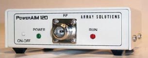
The PowerAIM 120
The Initial Check-Out
Once the unit was delivered, the first task at hand was turn it on, check it out, hook it to the laptop computer, find out what kinds of diagnostic displays it could produce, and how it was going to affect how I do antenna work.
The result? It only took a few test sweeps before I determined my OIB was going to be getting a great deal of rest. Being able to sweep the entire AM band in two minutes – and see the results – is something that would have taken an entire night with a bridge.
Even better, the PowerAIM does not seem to get squirrelly like an OIB will when you get into high-Z loads.
Right Into the Field
After getting used to it in the shop, the time had come to do some real work.
A diplexer I maintain had been getting a bit flaky, so my first project was to use the AIM to figure out what exactly was going on.
This first screen shot shown is a broad sweep of the 380-foot skirted antenna, used for a pair of diplexed stations on 1240 kHz and 1420 kHz.
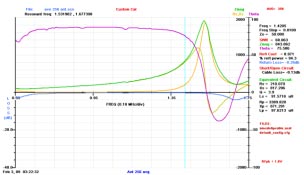
From the initial antenna sweep
From this first look I was able to see, for the first time, exactly how the antenna was reacting across the entire band.
It was easy to tell from the graph that the upper frequency carrier of 1.42 MHz was riding on the slippery up-slope heading. The base resistance at carrier was 210 Ohms, with a reactance of +817 Ohms – something quite difficult to read on my OIB but very clearly seen on the screen.
Checking the ATU Input
The next thing I looked at was the input to the ATU, and there I observed a rather interesting mess. Instead of 50 j 0, the transmission line was matching into 33 -j 13 Ohms.
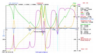
An interesting wideband sweep at the ATU input
I also noticed that this messy display changed drastically around the carrier frequency when I opened the J-plug leading to the far-side filters. That little tidbit let me know I had troubles in the far-side filters because there should have been little if any change if the filters were properly tuned.
In less than ten minutes, I had enough data to know what was wrong.
The PowerAIM was quite helpful in quickly zeroing in on the right part of the system.
Now the task at hand was to figure out exactly what was causing the problem. The PowerAIM was able to help with that, too.
Diagnosis
On the Power AIM display, an easy way to determine the resonate frequencies is to look and see where the theta (phase shift {magenta}) crosses zero.
The purple line shows the resonance at both operating frequencies
Measuring the series filter, I saw that the reject frequency had moved about 15 kHz from where it was supposed to be set.
When you think about how much energy would have been passing through that filter and then dumped by the shunt filter after the shifted series-reject filter, it made me wonder how I was even getting a signal on the air.
Dynamic Adjustments
Another screen displayed where the signal peaked or dipped, depending from which side of the trap you were looking.
With a few other tweaks and adjustments – verified by another quick sweep – and the diplexer was once again operating nicely. A quick run 3 out in the field, and an FIM showed that the station’s signal strength had increased as well.
This initial experience made me realize that any time you are running combined stations, doublechecking the tuning networks once or twice a year to make sure they have not drifted and caused serious signal loss is a good idea. A quick check could prevent many lost listeners.
On the Workbench
I also have seen many applications where the PowerAim can be useful aside from the antenna system.
Transmitter PA work comes to mind. Testing caps (for value) is another item you can do quickly; doing this over a wide frequency range seems to give a good indication of hidden troubles.
And, of course, you can see how the PowerAIM makes it easy to tune any ATU match point to any desired value.
Not Quite Alan-Ready
Probably my biggest complaint about the PowerAIM was how it was packed.
First of all, everything was mounted in a big Pelican case. In of itself, that was not bad; it was laid out to house and protect the PowerAIM along with a laptop computer, both power supplies, pockets for cables, and adaptors.
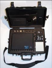
The PowerAIM package
Unfortunately, the case size in particular made this a setup that I will likely never use.
And I was really depressed to find there were no test leads nor computer cables are included as part of the package – you will need to provide your own RS-232 to whichever cable that you might need in order to interface the PowerAIM with your laptop.
I also discovered a rather frustrating to discover, odd quirk that was more of a computer issue. The PowerAIM would work just perfectly in the shop but when out in the field it would error out at a random spot during a sweep.
After several clouds of blue air, uttered over several months, I finally found the cause. One flick of the Wi-Fi switch on the laptop to disable it and the problem was gone. The problem was my computer had a native RS-232 port that was apparently interrupted whenever the Wi-Fi would decide to look for a friendly Access Port.
Making it Alan-Ready
To get the gear ready for use in the field in a way that I prefer, I pulled everything out of the Pelican case – and put it up on the storage shelf, perhaps for some other project.
Then I quickly made a test cable, using some RG-400 along with 1/4-inch flat braid and some 40 Amp clips.
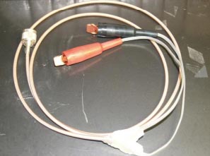
Some sturdy homemade test leads
Borrowing the precision OSL from an Anritsu Site Master, I was able to do several calibrations and save them for future use.
The AIM and battery fit nicely into a mid-size camera bag, complete with an RS-232 cable already attached and the battery all hooked up. Now when I go to deploy on a test all I need to do is connect the test cable to the front and plug the RS-232 cable to my laptop.
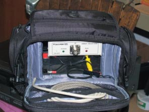
The custom “Made by Alan” bag
Fast, Easy Measurements
Before I made these modifications, it was taking me 15 to 20 minutes to get set up and make a measurement.
After moving everything to the camera bag, I could pull up to a site, make the measurements, and be back in my vehicle in five minutes.
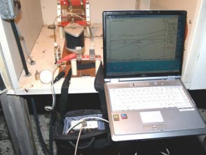
Drive right in, hook right up, and sweep the ATU
If I have to make a minor adjustment, who knows, it might be as much as ten minutes before I am ready to depart for the next adventure!
New Firmware, New Features
During the four years I have had my PowerAIM unit, the firmware has been progressing right along –adding new features a few times a year.
One of the features that I feel has evolved nicely is the TDR function, a feature that assists in diagnosing cable faults such as at an FM that was experiencing a hard VSWR fault with no visual indication of a problem.
This sweep showed that the fault was just a few feet from the transmitter end connector.
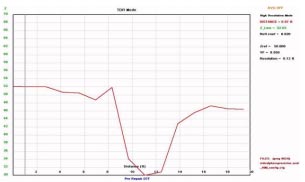
The fault was only 11 feet from the transmitter
Since no water was found in the line the Sawsall was used to open the line at the fault point where it was discovered that the spiral insulator had failed allowing the center to contact the outer.
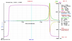
Not Just for the AM Band
By the way, the PowerAIM is not just for AM, with its frequency range going up to 170 MHz it is also quite handy in the FM band.
Using a good calibration load it is easy to get an excellent reading on an FM antenna. Here, you see a Shively antenna that had just been installed prior to it being tuned up.
Using the Smith Chart function along with a few markers, you can see exactly what the transmitter is seeing and know where to go to make the proper tweaks.
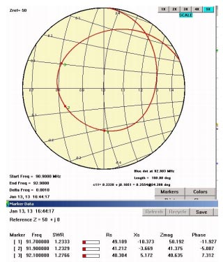
Furthermore, since the PowerAIM operates below one Watt of output, there is no problem sweeping while adjustments are being performed, and walking the antenna exactly where you want it.
Calibration is the Key
Keep in mind, any test equipment is only as good as the calibration. This holds true for the PowerAIM.
You need to know the limitations of your test configurations.
It is of the upmost importance that the unit is calibrated and verified for the measurement you are making. In the AM band the included calibration loads are sufficient, but I would not recommend them for FM work. For example, when testing with my home-grown AM test cable I know that it will only give valid readings below 10MHz and were not very accurate at the higher end of the PowerAIM’s operating range of 170 MHz.
With the PowerAIM, having several saved calibrations covering different bands and testing configurations is easily accomplished by saving the calibration files. To save time in the field, each test cable that you normally use will need to have its own calibration and saved files.
Nevertheless, any previously stored calibration should be verified before being trusted. This means that you should sweep the calibration load using your current test setup, including any test cables used, and confirm that the sweep accurately reads the load.
– – –
Alan Alsobrook is a regular contributor to The BDR. He is contract engineer based in St. Augustine, FL. Contact him at: aalso@bellsouth.net