Registered Plug? No, It’s A Jack!

[January 2025] Have you ever wondered how some of the connectors you use every day got their names? Some are easy, like the DB9 or the DB25, for example, but why is the RJ45 so named? Rolf has been looking into this topic.
Back when the Bell System was the mother of all US Telephony, Western Electric developed a system of telephone jacks that, in effect, live on today.
The first generation of removable phone jacks had very hard to remove large plugs and jacks with wiping spring connectors. These were bulky, hard to use, and expensive to manufacture.
When Mama Bell was forced to allow non-phone company equipment to be used on her phone lines, the FCC published the specs for interconnection (as provided by Bell) as Part 68. In addition to the electrical interface specifications, the Bell system of interconnection jacks was published as well.
Western Electric then designed a series of miniature modular jacks. These also had wiring contacts, but used much less contact pressure. Gold plating was introduced to keep corrosion down and maintain low resistance with the lower contact surface area and pressure. (Being miniature, the possibility of arc-over exists during abnormal events. While not a common problem, this aspect is worth keeping in mind when troubleshooting.)
USOC
The specifications were all integrated into the phone company’s Universal Service Order Code (USOC) system, intended to simplify ordering of specific telephone services.
A part of the USOC included specific Registered Jacks (yes, RJ = Registered Jack!). The FCC specifications called out these registered jacks as “miniature modular jacks.” While the registered jack specification included physical parameters such as dimensions and number of pins, the exact function of those pins also was part of the registered jack number, too, including features, such as hunting, call waiting, call forwarding, etc.
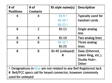
For example the RJ-11C or RJ-11W (“W” designating a wall jack) registered jack was used to deliver a single Plain Old Telephone Service (POTS) line, and utilized the center pins of a 6-position, 4-pin jack.
RJ-14C or RJ-14W was used to deliver 2 POTS lines on the same type of jack. The RJ-25C was the 3- line version, using a 6-position, 6-pin jack. Note that identical jacks had different RJ specifications.
The corresponding cables and plugs were not specified in the FCC standard, just the jack, which delivered the service.
RJ45
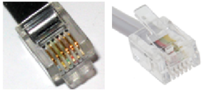
Another example of the registered jacks is the RJ-45.
Many folks do not know that this is actually a jack for 2-wire data service and is actually a keyed 8-position, 8-pin jack, not the unkeyed version now associated with that designation.

The RJ-48C is the unkeyed 8-pin, 8-position jack used for T1 service. It is the one now used for various data applications including Ethernet.
A LOT OF OPTIONS
Depending upon use and number of wires needed, there are dozens of registered jacks in existence, many with identical physical connectors.
All that said, certain common designations “stuck” and live on as connector types, independent of the service in question. So “RJ-11” is generally used for any 6-position, 4-pin jack, and RJ-45 is commonly used for any 8-position, 8-pin jack.
As a summary, the most common “RJ style” connectors as used in contemporary parlance are as follows (note that since there is no actual standard, some jacks used in identical fashion may have more than one ‘designation’):
PIN NUMBERING
Looking into a miniature modular jack (receptacle), with the pins at the top, the positions are numbered, starting from the left and increasing.
Since the original Registered Jack specs used the same miniature modular jacks in a variety of ways, the cable pair-to-pin assignment was not universal. Keeping in mind that there are jacks that have less pins than positions, this implies that the numbering may begin at some number other than 1.
For example, the RJ14 style is a 6-position, 4-pin jack. Therefore, it has no pin 1 or pin 6.
GOT A PAIR?
Telephone cable is twisted pair.
The telcos invented balanced audio, and when they went from open wire lines to cable, twisting of the conductors was an important innovation to reduce common mode interference by maintaining balance (actually, open wire had periodic transpositions which worked similarly).
As the rated “category” of the cable goes up the amount of twisting increases to increase common mode rejection. Note that the different pairs in a cable normally have varying twist pitches to reduce inter-pair cross talk.
When sending data over copper, split pairs (where a balanced signal is sent over one conductor of each of two different twisted pairs) is a significant problem that will cause data corruption. Even on analog applications it will increase noise and crosstalk as balance is not maintained. Simple continuity testing will not detect split pairs, so care is needed.
One must not make assumptions about how wiring is paired. This is especially true for patch cables.
MODERN TERMINOLOGY
So, what does all this mean today?
Today the term RJ-xx plug or RJ-xx jack are synonymous with the FCC term miniature modular jack of a certain number of positions and pins. As a pedant, your author greatly prefers to use the terminology x position, y pin miniature modular jack. I use RJ-X as a style description only.
For example, the pedantic designation for what most call an “RJ-11” plug or jack would be called 6-position, 4-pin miniature modular plug or jack (RJ-11 style).
And what most people would call an “RJ-45” plug or jack would be correctly referred to as an 8-position, 8-pin miniature modular jack, un-keyed (RJ-45 style).
SOME ADDITIONAL COLOR
While historically there were a number of color codes for outside multi-pair telephone cables, by far the most common is derived from the color codes devised for the first Plastic Insulated Cable (PIC). (See the sidebar at the end of this article for the details.)
In some variants background colors are solid without a stripe. That requires examining carefully what conductor it is twisted with. More commonly the background color has a thin strip of the foreground color to reduce confusion. ( Grey is called slate to give it a unique single letter code. ) ( See Remembering Those Color Codes )
WHEN YOU ARE IN THE ETHER
Here and now, in the 21st century the most important application of 8-position, 8-pin miniature modular jacks is for data.
Ethernet 10Base-T, 100BaseTX and 1000BaseTX all use the same 8-position, 8-pin connector (AKA RJ-45 style). Only 2 pairs (4 pins) are used for the earlier standards whereas 4 pairs (8 pins) are used for gigabit.
Datacom wiring standards have taken on their own evolution and standards. The standards are frequency bandwidth based and are intended to be agnostic to the actual protocols used. That said, Ethernet has become very much a defacto standard.
In any case, EIA/TIA set standards for the twisted pair cables themselves (the well-known “Category” standards) and the basic parameters for building implementation. Cable systems are laid out with horizontal backbones on each floor, and vertical risers between floors.
The general concept is that these are patched together (usually with modular patch cables, but cross-connect wiring is another option) as needed. The total length permitted for most Ethernet copper systems is 100 meters (328 feet). The horizontal and vertical cables are twisted pair with solid copper conductors.
Patch cables, used at the cross-connects, and between wall jacks and equipment, use stranded copper to allow flexibility without sacrificing durability. Note that the transmission performance of CatX solid conductor and CatX stranded conductor cables are not identical. The standards only allow limited amount of stranded cable due to its reduced transmission capabilities. Solid copper must be used for the installed wiring or performance will suffer.
A OR B STANDARD?
As with most standards, there were competing interests involved in the standardization process.
So, the adage “the best thing about standards is that there are so many to choose from” holds true here. Thus, there co-exists A and B standards for the colors of conductors and the corresponding pins on the jack-structured cabling RJ-45-style jacks, typically used for Ethernet.
To add to the confusion these two variants are part of the TIA/EIA-568-A standard. That means the complete designations are TIA/EIA-568-A 568A or TIA/EIA-568-A T568B. No, you cannot make this stuff up!
MORE STANDARDS
In addition to the TIA/EIA standards there are also “USOC Generic” and “USOC RJ61X” color code pairings. For anything other than Ethernet it is critical that you verify which standard should be used or split pairs will result.
If you are looking into the cavity of a jack (female) with the pins at the top, the pins for miniature connectors start at pin 1 to the left. The two standards for 4 pair data structured data (T1/E1 or Ethernet) cables on miniature modular jacks are as follows:
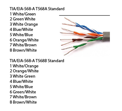
Of course, you can see that the two standards are electrically identical. As long as both ends are wired the same, it does not matter which you use. However, most facilities choose one and use it through the facility. B is most commonly used here in the USA.
Curiosity Note: It just so happens that if you wire one end of a patch cable to the A standard and the other end to the B standard it will act as an Ethernet (10 or 100 mbps) crossover cable.
Oh, yes. Memory. Can you remember the color sequence, so you keep them in order when wiring a large number of items? Check out this color helper.

https://www.nautel.com
JACK BE NIMBLE JACK BE QUICK
Recall that the permanently installed backbone cabling must be solid copper.
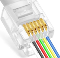
They would normally be terminated on both ends with a modular jack. The jacks have 110-style punch connectors that use an insulation displacement technology that forces the insulation aside and makes contact with the solid copper conductor inside. These jacks are not meant for use with stranded conductor cables.
The most common modular plugs, used for making patch cables, are only intended for use on stranded conductor cables. They typically have pins with two pointed prongs that pierce the insulation and bed themselves into the strands of the conductors. This type of plug will not work reliably with solid conductor cable (which would normally be terminated with a jack in any case).
There are special plugs that will work with solid conductors in the unusual case where this is desired. Instead of two prongs that are centered, there are 2 or 3 prongs arranged in a staggered fashion. These slide down the side of the insulation displacing it, rather than piercing it straight downwards. Combo stranded/solid plugs also exist.
The rule of thumb is that if plugs do not state otherwise, they are for use with stranded cable only. If you have the need to terminate solid conductor cable with plugs rather than jacks, make sure the plugs used are rated suitably or unreliability will result. Keep in mind that solid conductor small gauge wire will break after repeated handling and vibration, so stranded is preferred for non-installed cables (patch cables).
I intend a Part 2 of this series will present the basic generic “structured cabling concept” and the universal system it employs for cables, cross connects and jacks. We will also look at the most common patch cables (along with the pairing and colors codes), and some additional installation tips.
PLEASE DO NOT PUNCH ME
The contemporary 110-style punch blocks were the second generation of Bell-designed insulation displacement (IDC) terminal blocks.
The original 66 punch block concept originated as a labor-saving innovation when installing 1A2 Key systems where 3 pairs are needed to each line to each phone (plus a few additional pairs). It supports 20 to 26 AWG (gauge) solid copper conductors and was introduced by Western Electric (a Bell Company) in 1962. The 110 block was introduced in about 1979 and has largely replaced the 66 block.

There are a few other less common punch blocks as well, such as the Nortel BIX and the Euro Krone block. You must have the correct punch tool (or interchangeable blade) for each type of block.
The same 110 style terminals are used on most field installable RJ-45 style jacks. One nice feature of most 110 blocks are that they include the 5-pair foreground colors (Blue, Orange, Green, Brown, Slate) on protruding tabs which reduces mistakes and saves time when terminating cables. These tabs help separate the twisted pairs, so you can punch them, one conductor on each side of the tab.
Ideally, IDC connectors of all types should not be re-used. When doing so be sure to remove all bits of wire and insulation before re-use.
– – –
Some suggestions for additional reading:
Communications Cabling: https://archive.org/details/isbn_9780967163000
Mike’s Basic Guide to Cabling: https://openlibrary.org/books/OL8532084M/Mike
NFPA Volume 70; National Electric Code: https://www.nfpa.org/codes-and-standards/nfpa-70-standard-development/70
– – –
Rolf Taylor has over 30 years experience in dealing with operation and support issues. He currently is at Rocket Engineering and Consulting in Springfield, VA. You can connect with Rolf at rolf.taylor@yahoo.com
– – –
Would you like to know when more articles like this are published? It will take only 30 seconds to
click here and add your name to our secure one-time-a-week Newsletter list.
Your address is never given out to anyone.